


Hydraulic Pump Station System
Summary: The main products produced by the company include: hydraulic cylinders, hydraulic systems, earth pressure balance roadheader, mud water balance roadheader and water treatment and other non-standard complete sets of equipment, as well as pneumatic components, various types of shafts, disk processing parts
- Product Description
-
Usage and Features
The hydraulic pump station system is a working system where various hydraulic devices use hydraulic power as the core. It provides controllable direction, pressure, and flow of pressure media (such as mineral oil or water-glycol) to the action execution components (such as hydraulic cylinders and motors) according to work requirements, transmitted through pipelines, allowing the device to achieve various set actions and work cycles. Due to the diversity of control requirements for various hydraulic devices, our company conducts professional design and integration based on specific user needs.
Model Description
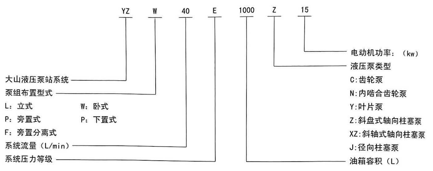
Pressure Level Code A B C D E F G H J K L M Pressure Range (MPa) ≤1.6 ≤2.5 ≤6.3 ≤10 ≤16 ≤20 ≤25 ≤32 ≤40 ≤50 ≤63 ≤80 Notes for Selecting Hydraulic Pump Station System
Basic Principles for Pump Group Layout and Selection

1. Side-mounted separate layout: The motor pump group is on an independent base installed on the side of the oil tank, suitable for high-power pump groups, easy to maintain.
2. Side-mounted layout: The motor pump group is installed next to the oil tank on a common base, suitable for reducing the height of the pump station and for larger power pump groups, easy to maintain.
3. Vertical layout: The motor pump group is installed vertically on the oil tank cover, mainly suitable for systems with small displacement positive displacement pumps working intermittently.
4. Horizontal layout: The motor pump group is installed horizontally on the oil tank cover, mainly suitable for hydraulic systems with good self-priming performance such as small displacement or variable displacement pumps.
5. Below-mounted layout: The motor pump group is located below the oil tank, mainly suitable for hydraulic devices used in field operations or to improve the pump's suction capability.
2. Working Medium and Temperature Conditions of the Hydraulic Pump System:
1. Working Medium: It is recommended to use anti-wear hydraulic oil, YB-N46.
2. Medium Temperature: The normal working temperature range is 35-60℃. If the temperature is below 15℃ or above 60℃, heating or cooling to the normal working temperature must be done in advance.
3. Specific Working Conditions: For high-temperature, flammable, and other working conditions, the requirements for the working medium need to be specified or recommended for targeted design.
3. Selection of Components for the Hydraulic Pump Station System
Situation 1: No specific requirements, our company prioritizes using various well-known domestic brands based on years of application experience.
Situation 2: If there are specific requirements or designated brands for various components, our company will design and manufacture according to the requirements.
4. Selection of Tank and Pipeline Materials for the Hydraulic Pump Station System
1. Ordinary Carbon Steel: Suitable for general hydraulic systems.
2. Stainless Steel: Suitable for precision hydraulic systems, salt mist, acid mist, and chemical environments.
5. Explanation of Oil Volume for the Hydraulic Pump Station System
The pump station system provides pressure oil to each action component during operation, requiring a large amount of circulating oil. If there are conditions such as shaking or tilting during operation, please specify when selecting.
6. Overall Protection, Handling, Outlet Direction, and Installation Requirements for the Hydraulic Pump Station System.
1. Based on the working conditions of the pump station system, consider protection against failure damage from other adjacent moving mechanisms during normal operation.
2. Whether there are specific requirements for the installation space size, on-site handling conditions, outlet direction, and foundation fixing method of the pump station system.
Cooling or Heating Methods and Selection for the Hydraulic Pump Station System
1. Cooling Methods and Selection
1) Natural Cooling: Cooling through the exchange between the surface of the oil tank and the air, suitable for intermittent work or small flow systems.
2) Forced Cooling: Using water (air) coolers for forced cooling, for long-term continuous work or large flow systems, the specific method needs to be selected based on the working conditions of the hydraulic device.
2. Heating Method Selection
1) Overflow Heating: For low-temperature conditions (<15℃), set the system pressure to 50% Pn, repeatedly start the motor several times, and use overflow heating to raise the working medium temperature by more than 20℃ before running the system.
2) Forced Heating: For cold low-temperature conditions, reasonably set the electric heater based on the system oil tank volume and heating time requirements, heat the working medium to above 20℃ before starting, and then preheat the pump and other devices by starting the motor before running the system.
8. Electrical Control Selection for the Hydraulic System
1. Control Method Selection:
1) Integrated electromechanical: The electrical control system (pump group power control system, valve control system) is integrated with the hydraulic pump station system.
2) Independent: The electrical control system is connected to the hydraulic pump station system through a junction box.
3) Control power for power supply voltage, frequency, electromagnetic coils, and other wiring devices.
Power supply voltage and frequency are AC380V, 50HZ.
Generally, the control voltage for the solenoid valve coil is:
1) AC220V
2) DC24V
In specific cases: Selection can be made according to the working conditions of the hydraulic device or the requirements of the country or region, and specific inquiries can be made to our company's technical department.
3) Explosion-proof requirements for motors, solenoid valves, and other wiring devices.
Generally: No explosion-proof requirements.
In specific cases: For hydraulic devices used in coal mine underground operations, specific chemical industry applications, etc., please consider the selection of explosion-proof requirements.
4) Selection of the protection level of the motor housing.
Generally: The protection level of the motor housing is IP44, which means:
1) Protection against solid objects larger than 1m: Can prevent wires or strips with a diameter or thickness greater than 1mm from touching or approaching live or rotating parts inside the housing; can prevent solid foreign objects larger than 1mm from entering the housing.
2) Splash-proof: Can withstand splashes from any direction without harmful effects.
In specific cases: Refer to GB/T4942.1 for the characterization numbers of the motor housing protection level; if there are no specific requirements for specific working conditions, selection should be made according to general conditions.
Key words:
Non-standard complete sets of equipment such as hydraulic cylinder, hydraulic system, earth pressure balance roadheader, mud water balance roadheader and water treatment, as well as pneumatic components, various shafts and plates
Product inquiry


Contact Information
Address: Wujian Town Industrial Park, Jiangdu District, Yangzhou City
Telephone:18932353788
E-mail:changweizhang@yzdsyy.com
Website QR Code
Copyright: Yangzhou Dashan Hydraulic Pneumatic Manufacturing Co., Ltd. Powered by www.300.cn SEO Tags

The main products produced by the company include: hydraulic cylinder, hydraulic system, earth pressure balance roadheader, mud water balance roadheader and water treatment and other non-standard complete sets of equipment, as well as pneumatic components, various types of shaft, plate processing parts.
- All
- Product Management
- News
- Introduction
- Enterprise outlets
- FAQ
- Enterprise Video
- Enterprise Atlas